last updated
Electrochemical cell and electrodes for cyclic voltammetry.
Demonstration by Dr. Alf Bacher; notes by Shadi Rezai
Chem 174, UCLA, Winter 2003
An simple electrochemical cell consists of two electrodes and an electrolyte. An electrode is the interface at which dissolved substrates may pick up or lose electron(s). An electrolyte is needed in order to provide electrical conductivity between the two electrodes.
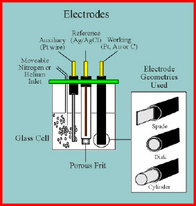
In a cell used for electroanalytical measurements e.g. cyclic voltammetry, anonic stripping voltammetry, etc there are always three electrodes due to the difficulties arising of the concurrent measurement of current and potential (see diagram below).
The first of the three electrodes is the indicating electrode also known as the test or working electrode. This is the electrode at which the electrochemical phenomena (reduction or oxidation) being investigated are taking place. The second functional electrode is the reference electrode. This is the electrode whose potential is constant enough that it can be taken as the reference standard against which the potentials of the other electrodes present in the cell can be measured. Commonly used reference electrodes are the silver-silver chloride electrode (Ag/AgCl/4M KCl, e=0.222 V) or the Kalomel electrode (Hg/HgCl/KCl). The final functional electrode is the counter or auxiliary electrode which serves as a source or sink for electrons so that current can be passed from the external circuit through the cell. In general, neither its true potential nor current is ever measured or known.
Electrochemical Cell
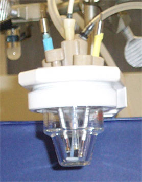
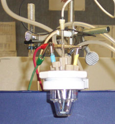
The normal material for cell construction is Pyrex glass for reasons both of visibility and general chemical inertness. The photograph shows a conventional three electrode cell showing the working electrode (left, glassy carbon), reference electrode (middle, Ag/AgCl) and auxiliary electrode (right, Pt-disk electrode). The cell lid is made from resistant PTFE plastic. A gas line for ebulliating the solution with nitrogen is also evident.
Experiment:
1. K3[Fe(CN)6] (analyte) is dissolved in a solution of 0.1 M KNO3 (electrolyte) solution and placed in a small glass cell (maximum filling level: 2/3). (In your case it will be the Mdtc3 compound in a solution of NEt4ClO4 in dry acetone)
2. A small stir bar is also placed in the glass cell
3. The cell is securely attached to the top part (plastic) using the white plastic piece
4. The stirring is started
5. The entire setup is connected to a nitrogen line. Open the main regulator at the tank and the valve that goes to setup. A smooth bubbling should be observed in the cell. The flow rate should not be too high, because it will cause the solution to leak from the cap of the cell. Note: turn off the N2 line and stirring when do the reading
6. Connections: Red wire to Platinum electrode, Green wire to Graphite, White wire to reference electrodes (here Ag/AgCl/4 M KCl/H2O)
7. Set up experiment on computer
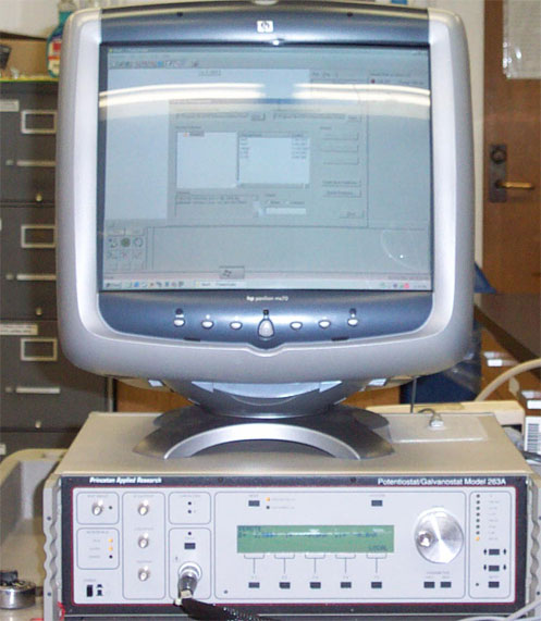
a. Start Power Suite
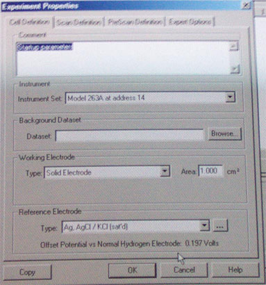
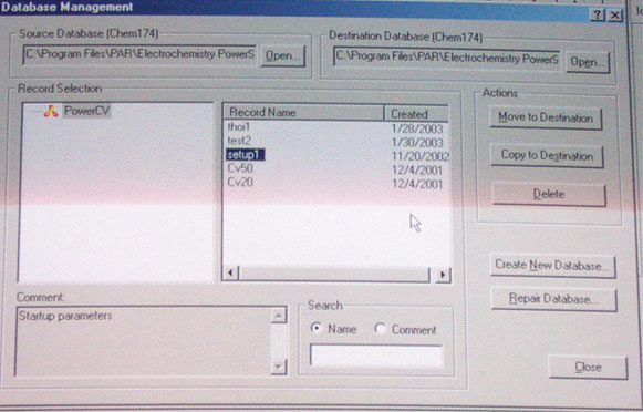
b. Load default parameter from Chem 174 directory (file: setup1, see above)
c. Make sure that you erase the previous data points (Edit-Select all and Delete points). Check the parameters.
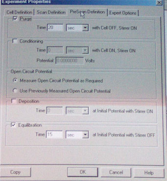
d. Click on the Run button to start the experiment. A little status window informs you about the progress of the experiment. When it goes from purging to equilibration time, discontinue the stirring and turn off the nitrogen flow.
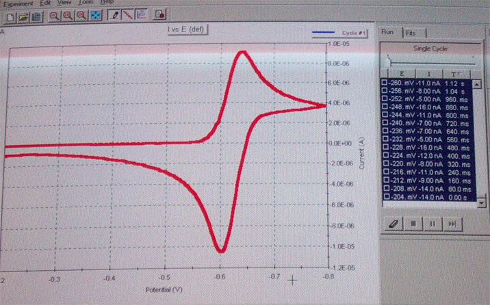
e. After the run is completed, you should see a graph as shown in the reader or below. Save the data in the Chem 174 folder.
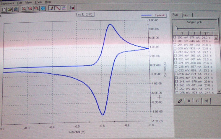
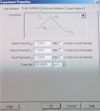
f. The next step is to zoom in on the observed peaks. First you need to erase the data points (see above). To set new parameters go to Experiment Properties/scan definitions. Define a new lower and upper margin for the scan which should be ~200 mV above and bow the peak in question. Perform another run as described in d.